How to Create a DFMEA: Step-by-Step Guide with Examples
Prerequisites — What You Need Before Starting
Let's get one thing out of the way: a DFMEA does not begin when someone opens Excel.
A useful DFMEA starts with engineering context. If your team jumps straight into scoring Severity, Occurrence, and Detection before defining the system, functions, and interfaces, you'll end up with a worksheet full of impressive-looking nonsense.
Before you start, gather these inputs:
- system or product scope
- block diagram or structure tree
- key functions and performance requirements
- interface assumptions
- known environmental conditions
- preliminary schematic or architecture
- validation assumptions or current test strategy
- a small cross-functional team if possible
For hardware teams, that usually means at least one design engineer, someone with system knowledge, and ideally someone who understands test, reliability, manufacturing, or field usage.
The modern automotive-oriented method most teams reference today is the AIAG & VDA 7-step approach from the 2019 handbook. Even if you are not in automotive, the structure is still useful because it forces logical traceability from system structure to function, from function to failure, and from risk to action.
Before diving into the steps, it helps to review the basics in What is FMEA? A Practical Guide for Hardware Engineers.
Step 1 — Structure Analysis (Define Scope & System Boundaries)
The first step is to define what exactly you are analyzing.
That sounds obvious, but weak DFMEAs often fail right here. Teams say they are analyzing "the temperature sensor circuit," but they do not agree whether that includes the thermistor, the divider, the MCU ADC input, the power supply, the connector, the harness, or the software interpretation of the ADC value.
In structure analysis, you identify the system, subsystem, and element relationships.
For a simple temperature sensing path, the structure might look like this:
- System: Temperature monitoring function
- Subsystem: Sensor input circuit
- Elements: NTC thermistor, voltage divider resistor network, decoupling capacitor / filtering element, PCB trace and connector path, MCU ADC input
The goal is to define boundaries clearly enough that everyone is analyzing the same thing.
A few practical rules:
- include interfaces, not just parts
- define what is inside the scope and what is outside
- use a block diagram if possible
- do not collapse everything into one box called "circuit"
This matters because later steps depend on these relationships. If the structure is muddy, the function analysis and failure logic will be muddy too.
Step 2 — Function Analysis (What Should Each Element Do?)
Once you know the structure, ask: what is each element supposed to do?
This is where a lot of teams get lazy. They write "thermistor" under function. That is not a function. That is a part name wearing a fake mustache.
Functions should be expressed as actions or intended behavior.
Examples:
- NTC thermistor: change resistance as temperature changes
- voltage divider: convert resistance change into measurable voltage
- decoupling/filter capacitor: reduce noise on the sensed signal
- ADC input: convert analog input voltage into digital measurement
- overall sensing path: report temperature within required accuracy and response time
Good function analysis creates a bridge between design intent and failure logic.
It also helps to define requirements here: operating range, accuracy target, fault tolerance expectations, response time, supply range, temperature range, noise tolerance.
If a function has no requirement, it is hard to say whether it failed.
Step 3 — Failure Analysis (What Can Go Wrong?)
Now we get to the part engineers expect: failure modes.
At this step, ask what can go wrong at each relevant level.
For the temperature sensor circuit, examples include:
- thermistor open circuit
- thermistor short circuit
- divider resistor drift
- solder crack at sensor terminal
- ADC input leakage or clamp behavior under fault
- noise coupling into sense trace
- decoupling capacitor open
- incorrect resistor value stuffed
- connector intermittent contact
But do not stop at naming physical defects. Tie them back to function.
For example:
- Failure mode: thermistor open
- Functional consequence: divider output rises toward rail
- System behavior: ADC reads maximum or near-maximum
- User-level effect: false high-temperature alarm or false shutdown
This is the key discipline: failures should be written in a way that supports traceability from element to function to effect.
A useful working question is: "If this element stops doing what it is supposed to do, what happens next?"
That "what happens next" chain is the backbone of a good DFMEA.
Step 4 — Effect Analysis & Severity Rating (S)
Once you identify a failure mode, describe the effect.
Effects can be considered at multiple levels:
- local effect
- next higher level effect
- end effect at system or user level
For our thermistor-open example:
- local effect: divider output goes high
- subsystem effect: ADC reading saturates high
- system effect: temperature calculation becomes invalid
- end effect: false over-temperature warning, derating, or shutdown
Now rate Severity (S).
Severity reflects how serious the effect is, not how often it happens.
For an example scoring approach:
- S = 9 if the false reading could trigger unnecessary system shutdown in a safety-relevant application
- S = 7 if it causes significant functional degradation or false fault response
- S = 4 if it only causes moderate inconvenience with no safety or compliance impact
The exact scale depends on your organization's criteria, but the principle is stable: severity belongs to the consequence.
A common mistake is lowering severity because "the fault is unlikely." That is wrong. Low occurrence does not make a severe effect less severe. It just makes it less frequent.
Step 5 — Cause Analysis & Occurrence Rating (O)
Next ask: why would this failure mode happen?
For thermistor open, possible causes include:
- cracked solder joint from thermal cycling
- wire break near strain point
- connector fretting
- assembly damage
- incorrect part or weak land pattern
- excessive mechanical stress
Now rate Occurrence (O) based on how likely the cause is to happen, given the design, environment, and historical evidence.
For example:
- O = 4 if the cause is plausible but mitigated by proven design practice
- O = 6 if the environment makes the failure reasonably likely over life
- O = 2 if the cause is rare and strongly prevented by design margin and validation evidence
Occurrence is where teams are often tempted to guess. Resist that. Use: prior field history, test data, known failure physics, manufacturing maturity, environment exposure, component quality evidence.
If you have no data, be explicit that the score is provisional.
Step 6 — Current Controls & Detection Rating (D)
Now identify the controls that currently exist to either prevent the cause or detect the failure before it reaches the customer.
Typical current controls in a hardware DFMEA might include:
- schematic review
- design rule checks
- tolerance simulation
- end-of-line test
- firmware plausibility checks
- ADC out-of-range detection
- continuity check
- HALT / environmental validation
- fault injection test
For our thermistor-open case, you might list:
- firmware plausibility check for impossible temperature jump
- ADC high-limit diagnostic
- continuity test during production
- design review of sensor harness routing
Then assign Detection (D).
Detection answers: how likely is the current control to catch the issue before the user experiences the effect?
Example interpretation:
- D = 2 if the control is highly effective and directly detects the fault
- D = 5 if detection is partial or indirect
- D = 8 if the current design has little reliable detection capability
A common trap: calling something a control when it is really a hope. "Engineer is experienced" is not a control. "Will probably be caught in testing" is also not a control unless there is an actual test with defined coverage.
Step 7 — Action Priority (AP) and Risk Evaluation
This is where modern practice differs from older spreadsheet culture.
Historically, many teams multiplied S × O × D to get an RPN and sorted the worksheet by that number. The problem is that the math can hide important cases. A high-severity problem may get a moderate RPN if occurrence or detection is scored favorably. Different combinations can land on the same RPN while meaning very different things.
The AIAG & VDA 2019 method instead uses Action Priority (AP) to guide decision-making. Rather than pretending one multiplied number captures all engineering judgment, AP emphasizes whether action is strongly recommended based on the pattern of Severity, Occurrence, and Detection.
For practical use, many teams interpret AP in three levels:
- High — action is strongly recommended
- Medium — action is recommended based on engineering judgment
- Low — action may not be needed beyond current controls
A simplified example:
- S=9, O=4, D=6 → AP: High
- S=7, O=3, D=4 → AP: Medium
- S=4, O=2, D=3 → AP: Low
The exact classification should follow your organization's AP table derived from the handbook. The important point is this: Do not let a neat-looking number replace engineering judgment.
If you want the standards background behind AP, see FMEA Standards: AIAG & VDA, IEC 60812, and Industry Requirements.
Step 8 — Optimization (Define Actions & Re-evaluate)
A DFMEA is only useful if it changes something.
Once you identify a high- or medium-priority item, define actions that reduce Occurrence, improve Detection, or sometimes eliminate the failure path entirely.
For the thermistor-open case, possible actions include:
- add pull-up/pull-down architecture that forces a diagnosable fault state
- implement firmware rationality checks and sensor-open diagnostics
- improve connector strain relief
- revise PCB layout or solder pad design
- add fault injection validation for open/short conditions
- tighten component or assembly controls
Then re-evaluate the row after the action is implemented.
Before action:
- Failure mode: thermistor open
- Effect: false high-temp alarm / false shutdown
- S = 9, O = 4, D = 6
- AP = High
After action:
- Added ADC diagnostic threshold and open-circuit detection logic
- Improved harness strain relief
- Added validation test for open sensor fault
- Re-evaluated: S = 9, O = 3, D = 3
- AP = Medium or Low depending on criteria
Notice that Severity stayed the same. That is normal. The consequence of the fault is still serious. What changed is the likelihood and the ability to detect it.
This is one of the most important habits in DFMEA work: actions should be tied to a credible mechanism for changing the risk pattern.
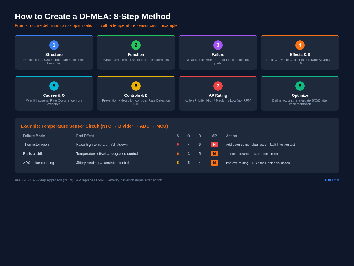
Practical Example: DFMEA for a Temperature Sensor Circuit
Let's build a compact example around this sensing chain: NTC thermistor → voltage divider resistors → decoupling/filter capacitor → MCU ADC input.
Function of the circuit: The circuit should measure temperature and provide a stable voltage to the ADC so the MCU can calculate temperature within the required accuracy.
Row 1 — Thermistor open
- Function: sense temperature via resistance change
- Failure mode: thermistor open
- Effect: ADC reads near full scale, interpreted as extreme temperature
- End effect: false high-temperature alarm or false shutdown
- Severity: 9
- Cause: solder crack, wire fatigue, connector issue
- Occurrence: 4
- Current controls: design review, continuity test, firmware plausibility check
- Detection: 6
- AP: High
Possible action: add explicit open-sensor diagnostic threshold, strengthen strain relief and solder joint robustness, validate with injected open-fault testing.
Row 2 — Divider resistor drift high
- Function: scale thermistor resistance into ADC voltage range
- Failure mode: resistor drift changes divider ratio
- Effect: temperature reading offset
- End effect: inaccurate thermal control, degraded performance
- Severity: 6
- Cause: poor resistor tolerance, long-term drift, wrong part loaded
- Occurrence: 3
- Current controls: BOM review, tolerance analysis, incoming quality controls
- Detection: 5
- AP: Medium
Possible action: use tighter tolerance / better tempco resistor, add calibration or plausibility range checks, strengthen component verification process.
Row 3 — Noise injected into ADC input
- Function: provide stable analog signal to ADC
- Failure mode: excessive coupled noise
- Effect: jittery temperature reading
- End effect: unstable control behavior or nuisance diagnostics
- Severity: 5
- Cause: poor routing, weak filtering, shared noisy return path
- Occurrence: 5
- Current controls: layout review, decoupling capacitor, bench testing
- Detection: 4
- AP: Medium
Possible action: improve trace routing and grounding, adjust RC filter design, add noise-focused validation under realistic load conditions.
This example is intentionally simple, but the pattern scales. The same logic works for battery sensing, pressure sensors, motor drivers, power rails, and mixed-signal interfaces.
And yes, this is exactly the kind of repetitive analysis that tools can help accelerate—especially Steps 3 through 7—if the structure and function definitions are already clear.
If you want a starting worksheet, a good next step is to use an FMEA template.
FAQ
Q: How do you create an FMEA step by step?
A: A practical DFMEA flow is: (1) define structure and boundaries, (2) define functions, (3) identify failure modes, (4) analyze effects and rate severity, (5) analyze causes and rate occurrence, (6) identify current controls and rate detection, (7) evaluate action priority, (8) define actions and re-evaluate.
Q: What do I need before starting a DFMEA?
A: You need at least a defined scope, system structure, intended functions, and enough design context to understand interfaces and assumptions.
Q: Is RPN still the best way to prioritize DFMEA actions?
A: Not usually. Modern automotive-oriented practice favors Action Priority (AP) rather than relying only on RPN, because AP better reflects the practical meaning of Severity, Occurrence, and Detection combinations.
Q: Can a small hardware startup do DFMEA without a big quality department?
A: Yes. A small team can do very effective DFMEA if the scope is clear, the worksheet is tied to real design functions, and the discussion stays specific rather than bureaucratic.
Q: What is a good first example for learning DFMEA?
A: A simple sensing or power circuit is a great starting point because the functions, interfaces, and common fault behaviors are easy to understand and explain.
Try EXITON FMEA — Free for 30 Days
Generate AIAG & VDA compliant DFMEA from your KiCad schematic. No credit card required.
Download Free Trial